Thinking out-of-the-box
Looking at the market today, and you can find a range of construction design CAD packages available, many of which present features dedicated to improving performance and lowering the 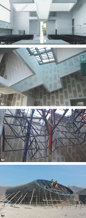 possibility of errors.
In the domain of steel construction in particular, some CAD packages allow the designer to easily position a component – for example a universal I beam type – within an assembly drawing. Connections at either ends of the components can be chosen from a library or designed Once the components have been added to the assembly model and their end connections defined, the CAD system can export the model and drawing of each component with the right length and connection details at both ends.
That is very helpful, but it still requires the user to define a full assembly and handle each of its components manually, before the system can export their geometry and create drawings. When a project involves thousands of components, few or none of which are identical to each other, manually adding them to an assembly can still be a challenge, take a long time and increase the risk of making mistakes.
The first solution
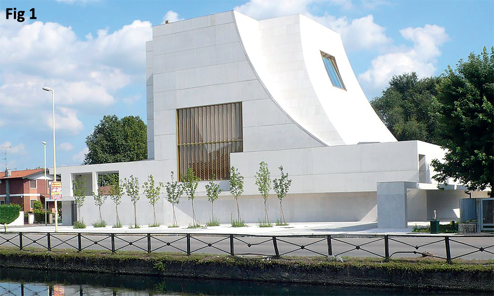
The first project which required Roberto’s CAD innovation involved the design of a 3D spatial cross structure for the new church of San Gianna Beretta Molla, built in Trezzano SN, near Milan, Italy in 2012) [Fig 1].
“The architects had conceived an impressive 3D spatial structure, with the section of a cross, hanging from the ceiling and projecting the light entering through its glass roof onto the believers in church below. The cross structure was to be covered in drywall, therefore it needed to be very strong and rigid (in order to avoid cracks) and extremely light [Fig 2 and Fig 3]. I proposed a truss structure made of very light folded U channels: it would be rigid and strong enough, and it would also present flat, regular faces for applying the drywall, a very welcome bonus [Fig 4],” explained Roberto.
After having been FEM verified, the structure needed to be designed for fabrication and Roberto decided it was time for engineering a much simpler and quicker design approach. Time was of the essence, and manually designing the required components – just over 500 in this instance – would have taken too long.
“Therefore, I divided each of the 12 cross walls into five smaller trusses,” he said. “Once the first truss had been designed, a routine was built into the 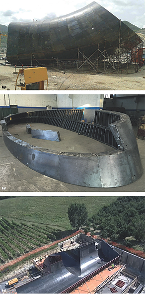 CAD to automatically place it in the assembly at the right position according to its mark ID. Another routine could generate all the remaining trusses from the first one, by using it as a master model. After positioning each new truss in the assembly, the routine would automatically model it according to its needed size.”
Similarly, once a detailed drawing had been drafted for the first truss and its components, detailed drawings were automatically available for all remaining trusses and their components. In other words: 60 different trusses and more than 500 components automatically modelled and drafted after having modelled and drafted just one truss and a handful of components.
Thanks to the automated process, once the accuracy of the first truss had been double checked, all remaining trusses were generated automatically without possibility of error. The design had been conceived for quick manufacturing as well as simple on site assembling. Consequently, the project was a great success for all parties involved.
Problem solving
Roberto (who is in the top percentile of his field) then brought this expertise and technology to the UK where he founded Wenlock in 2015. Since then, a lot of Wenlock’s projects have gained considerable benefit from this technology and a few of them would not have been possible without it.
“A good example of this is for a project that involved the design of two different sets of formworks for the draft tubes of the Grand Ethiopian Renaissance Dam (GERD),” added Roberto. “Hydroelectric power plants often have less than five turbines, and hence less than five draft tubes. Consequently, due to cost and to their very irregular shape, draft tube formworks are often build on site with wood, through an approximate and labour intensive operation. For the GERD, it being a large dam with 16 turbines of two different types, the most convenient option was fabricating steel formworks. Using its customised CAD technology, Wenlock divided each draft tube formwork in 22 rings, each comprising 24 blocks: 528 unique blocks [Fig 5, Fig 6 and Fig 7].”
Accounting for about eight to 14 plate components for each block, depending on shape and size, the number of unique plates to be laser cut, folded, and handled was over 5000.
It became immediately obvious that manually handling the design of more than 5000 plates, albeit with the help of 3D CAD systems, was not feasible. By applying Wenlock’s design approach, each block was automatically positioned within the assembly and generated by applying a routine to a single master model. Each block’s component was shaped on the outer (concrete) side by the draft tube surface. “Since each block, being automatically generated, was created relative to the same absolute co-ordinate system, its shaping surface had to be re-positioned, by the automatic routine, according to the linear transformation defined by the actual position of the block in the assembly relative to the absolute coordinates. The result: more than 5000 components and more than 500 assemblies modelled and drafted automatically!” Roberto revealed.
Once the design was accomplished, it was soon clear that fabrication would not be easy. Actually, with each block lacking even two sides orthogonal to each other, fabrication would have been impossible with conventional methods. Wenlock stepped in again, and devised a method for assembling and tack welding the blocks using an industrial robot in a very unconventional way: but that is a story for another day!
Conclusion: thanks to Wenlock’s design technology, a project which was deemed almost impossible turned out to be very successful and profitable.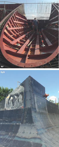
Wenlock has also worked its magic on another interesting project, this time in Italy. Using the same technology, this featured a 350sqm soffit formwork designed for a winery project in the Cuneo province in Piedmont [Fig 8 and Fig 9].
This massive formwork, having the shape of two intersecting tunnels upside down, albeit less irregular than the draft tube one, presented the difficulty of having to achieve a perfect match among 540 panels, including the intersection line [Fig 10]. Once again, Wenlock’s design technology enabled it to automatically model and draft more than 6000 components and 540 assemblies after having defined only two master models (one for each tunnel trunk).
By combining an interest in 3D design and a knack for innovation, Roberto Garziera and the team at Wenlock continue to address challenging builds around the world. Specialising in the design of bespoke machinery and devices, special equipment, steel constructions, and industrial products, Wenlock’s expertise is increasingly being called upon for challenging and unusual projects.